Interrupts
An interrupt is a process of creating a temporary halt during program execution and allows peripheral devices to access the microprocessor.
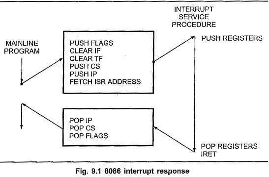
The microprocessor responds to these interrupts with an interrupt service routine (ISR), which is a short program or subroutine to instruct the microprocessor on how to handle the interrupt.
There are different types of interrupt in 8086:
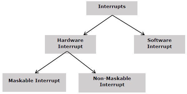
Hardware Interrupts
Hardware interrupts are that type of interrupt which are caused by any peripheral device by sending a signal through a specified pin to the microprocessor.
The Intel 8086 has two hardware interrupt pins:
- NMI (Non-Maskbale Interrupt)
- INTR (Interrupt Request) Maskable Interrupt.
NMI: NMI is a single Non-Maskable Interrupt having higher priority than the maskable interrupt.
- It cannot be disabled (masked) by user using software.
- It is used by the processor to handle emergency conditions.
For example: It can be used to save program and data in case of power failure. An external electronic circuitry is used to detect power failure, and to send an interrupt signal to 8086 through NMI line.
INTR: The INTR is a maskable interrupt. It can be enabled/disabled using interrupt flag (IF). After receiving INTR from external device, the 8086 acknowledges through INTA signal.
It executes two consecutive interrupt acknowledge bus cycles.
Software Interrupts
Some instructions are inserted at the desired position into the program to create interrupts. These interrupt instructions can be used to test the working of various interrupt handlers. It includes −
INT- Interrupt instruction with type number
It is 2-byte instruction. First byte provides the op-code and the second byte provides the interrupt type number. There are 256 interrupt types under this group.
Its execution includes the following steps −
- Flag register value is pushed on to the stack.
- CS value of the return address and IP value of the return address are pushed on to the stack.
- IP is loaded from the contents of the word location ‘type number’ × 4
- CS is loaded from the contents of the next word location.
- Interrupt Flag and Trap Flag are reset to 0
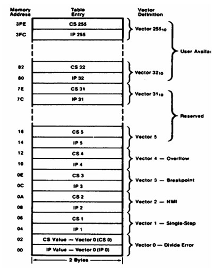
The starting address for type0 interrupt is 000000H, for type1 interrupt is 00004H similarly for type2 is 00008H and ……so on. The first five pointers are dedicated interrupt pointers. i.e. −
TYPE 0 interrupt represents division by zero situation. [ TYPE 0 (division by zero)]
TYPE 1 interrupt represents single-step execution during the debugging of a program. [TYPE 1 (single step execution for debugging a program)]
TYPE 2 interrupt represents non-maskable NMI interrupt. [TYPE 2 represents NMI (power failure condition)]
TYPE 3 interrupt represents break-point interrupt. [TYPE 3 (break point interrupt)]
TYPE 4 interrupt represents overflow interrupt. [TYPE 4 (overflow interrupt)]
The interrupts from Type 5 to Type 31 are reserved for other advanced microprocessors, and interrupts from 32 to Type 255 are available for hardware and software interrupts.
INT 3-Break Point Interrupt Instruction
It is a 1-byte instruction having op-code is CCH. These instructions are inserted into the program so that when the processor reaches there, then it stops the normal execution of program and follows the break-point procedure.
Its execution includes the following steps −
- Flag register value is pushed on to the stack.
- CS value of the return address and IP value of the return address are pushed on to the stack.
- IP is loaded from the contents of the word location 3×4 = 0000CH
- CS is loaded from the contents of the next word location.
- Interrupt Flag and Trap Flag are reset to 0
INTO - Interrupt on overflow instruction
It is a 1-byte instruction and their mnemonic INTO. The op-code for this instruction is CEH. As the name suggests it is a conditional interrupt instruction, i.e. it is active only when the overflow flag is set to 1 and branches to the interrupt handler whose interrupt type number is 4. If the overflow flag is reset then, the execution continues to the next instruction.
Its execution includes the following steps −
- Flag register values are pushed on to the stack.
- CS value of the return address and IP value of the return address are pushed on to the stack.
- IP is loaded from the contents of word location 4×4 = 00010H
- CS is loaded from the contents of the next word location.
- Interrupt flag and Trap flag are reset to 0
Interrupt pointer table for 8086
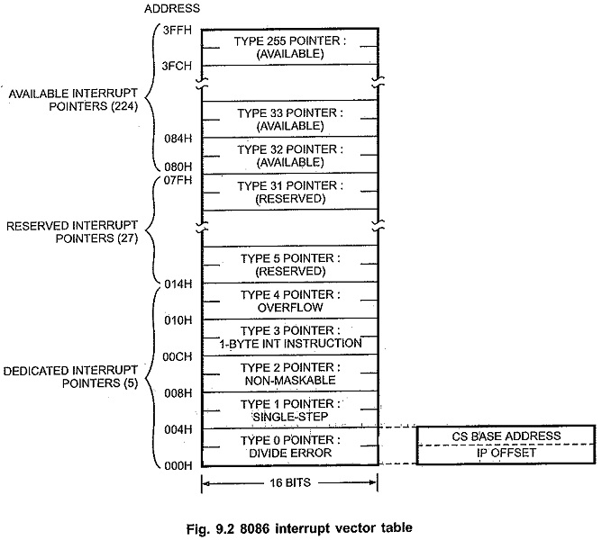
The 8086 can handle up to 256, hardware and software interrupts.
1KB memory acts as a table to contain interrupt vectors (or interrupt pointers), and it is called interrupt vector table or interrupt pointer table. The 256 interrupt pointers have been numbered from 0 to 255 (FF hex). The number assigned to an interrupt pointer is known as type of that interrupt. For example, Type 0, Type 1, Type 2,...........Type 255 interrupt.


Comments
Post a Comment